J-20 and its tail feathers


The X-29 has strake flaps, MiG-1.44 has them too, they are used for pitch up control they are also known as "back-porch" or "aft-strake" it is a horizontal control surface that is incorporated into a faired extension of the wing or fuselage. This device, seen on the X-29, is mostly used to prevent pitch up but can also serve as a primary pitch control surface in some cases.
The tail boom and wing trailing edge root extension on J-20 are chiseled for stealth needs, however they have no hinges as in the MiG 1.44`s wing trailing edge extensions, also known as strake flaps, further more they are not as thin and they have a more abrupt end than the thinner and smoother trailing edge extensions of the MiG 1.44

J-20 has made some compromises for the sake of stealth and the all moving vertical tail more or less does a very good job, however there are compromises that affect it, for example on MiG-1.44 has a mid-wing; while on the J-20 it is a high wing, on the MiG the wing trailing edge extension (also known as strake flaps ) is thin and is hinged but on the J-20 the same part is chiseled for stealth purposes and is not thin due to the fact is a high wing and it is a continuation of the lateral engine nacelles wall, these will generate more drag and turbulence due to the fact the abrupt change the flow will have there; in the Russian machine the strake flaps are really part of the wing and at the trailing edge extension generate less drag, however in the Chinese machine, a smaller dorsal vertical tail generates relatively less drag and it is better for stealth.
On the vertical ventral fins, the Russian machine has hinges working like rudders, thus helping more than the ones on the J-20.
So far the Chinese designed a good tail, but the trailing edge extensions of J-20 will generate too much drag, but they will allow a relatively good transition for the wing fuselage blending at the aft part of the aircraft however they will not generate so much lift as in the case of the Russian aircraft due to higher drag generation. the ventral fins on J-20 also will not be as effective as the ventral fins of the MiG, because at High Angles of Attack, the hinged ventral fins of the MiG will allow more controlability, and the MiG`s taller dorsal fins will be less blanketed by the fuselage than in the J-20`s dorsal vertical stabilizers case.
In order to understand its tail configuration we have to see that It is known that vertical tail surfaces placed outboard on the wings give good lateral-directional stability due, to favorable interference with wing vortices, nevertheless they may cause aero-elastic problems. The In-board canting of vertical tails are known to be unstable in lateral-directional control, but out-board canting is found to be favorable.
All-moveable twin vertical tails are known to provided a substantial increase in yaw control over conventional rudders and thus they extend roll coordination capability to higher angles of attack. But it is possible, the adverse roll generated by all-moveable vertical tails can present a potential problem, this will depend on the level of roll acceleration the aircraft requires and the roll control available from other of its surfaces.
This is known as a ventral fin or strake. ... The ventral fin is added when the fuselage shields so much of the vertical stabilizer at higher angles of attack that a fin is appended to the belly. This is often used to prevent yaw, especially in twin-engine aircraft where only one engine is operating
The ventral fin is not blanketed even with high angles of attack. The ventral fin also serves to prevent lateral instabilities in high-speed flight
A twin tail can be used if a single vertical tailplane would be too big. Twin tails are covered less by the front fuselage in the case of high angles of attack than a vertical tail in the plane of symmetry. For the latter reason twin tails are seen on fighter aircraft that operate in the high angel of attack range. F
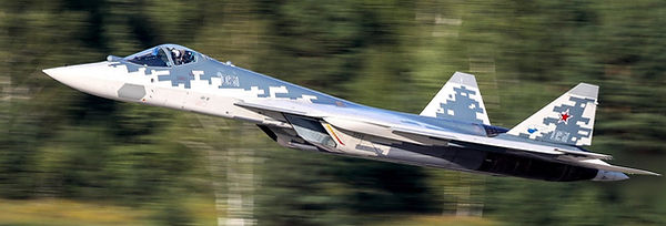
While the stealth vertical fins treatment on J-20 is better than the MiG 1.44`s, the aerodynamic effectiveness is more or less the same, however it is slightly better on the MiG 1.44 thanks to the fact the hinged ventral fins of the MiG-1.44 will also operate as regular rudders, however J-20 is inferior to the results on Su-57, thanks to the fact Su-57 uses thrust vectoring as pitch and yaw controls, eliminating the need for ventral fins.
For longitudinal pitch control the wing trailing edge extension, also known as strake flaps, can utilize either a plain flap or a slotted flap, and both are capable of deflecting up and down.
The two concepts do provide the same amount of nose-up pitching moment allowing the configuration to be trimmed to , about 40 degrees of angle of attack.

Su-57 can use its LEVCONs for roll control and its Thrust vectoring for trim, pitch, yaw and roll control, basically eliminating the need for ventral vertical fins, improving the stealth of Su-57.
The LEVCON eliminates the drag, canards cause by their downwash over the main wing, while at the same time being able to control the lift and vortex system over the wing, generated by the Leading edge extensions of the wing-LEVCON structure.


J-20 can use its canted vertical tails as a V tail, it can use them with elevator inputs, rudder inputs or combined as rudder-elevator inputs. A V-tail has two control surfaces that combine aircraft yaw control and pitch control. Canted surfaces reflect the radar away from the source, aiding in stealth.
A V-Tail aircraft design incorporates two slanted tail surfaces instead of the horizontal and vertical fins of a conventional aircraft empennage. The two fixed tail surfaces act as both horizontal and vertical stabilisers and each has a moveable flight control surface referred to a ruddervator. These ruddervators perform the combined functions of both a rudder and an elevator.
When the pilot moves the control column forward or aft, the ruddervators move symmetrically in the same manner as a conventional elevator. Conversely, when the rudder pedals are displaced, the ruddervator surfaces move differentially to emulate the movement of a conventional rudder. when both the rudder pedals and the control column are moved simultaneously, an incorporated mixing mechanism moves each surface an appropriate amount.
COMBINED ELEVATOR-RUDDER INPUTS
On the V-tail, Thus, the sum of the vectors is the resultant that will determine if it is an elevator input, rudder input, or a combined rudder-elevator input with asymmetric deflections.
J-20 can use its all moving vertical tails, for yaw, and pitch control, it can use them simultaneously for directional control in yaw and pitch.
However they work in combination of other aerodynamic control surfaces, such as the wing control surfaces.
J-20 has vertical fins that work, allowing differential ruddervator displacement, this allows combined elevator-rudder inputs.
http://www.beechcraft.org/vtail/eckalbar/rudder.html
This is not uncommon other fighters like F-18, F-35 or Su-57 can do it too.
The F-35 can use its canted fins for pitch up control using elevator inputs by deflecting both rudders up forcing the tail down and the nose to pitch up.
The vertical tails on F-35A or J-20 can be used as rudders for yaw control and as tailerons for pitch up or pitch down the aircraft, this also reduces the deflection of the tailerons to pitch the nose up on F-35A.
However they can be used to do both functions, at the same, time with rudder-elevator inputs
https://people.clarkson.edu/~pmarzocc/AE430/AE-430-4.pdf
Due to the aircraft symmetricity requirement about x-z plane, an aircraft with one vertical tail is not allowed to have any dihedral angle. However, if the aircraft has a twin vertical tail, (such as few fighters), the dihedral angle has positive contributing to the aircraft lateral control. But it reduces the aerodynamic efficiency of the vertical tails, since two vertical tails will cancel part of their lift forces. In addition, the vertical tail dihedral angle will contribute to detectability features of the aircraft. For instance, McDonnell Douglas F-15 Eagle twin vertical tails canted 15 deg to reduce radar cross section. The exact value for the dihedral angles of a twin vertical tail is determined in the overall aircraft lateral- directional stability analysis process.http://www.aero.us.es/adesign/Slides/Extra/Stability/Design_Tail/Chapter%206.%20Tail%20Design.pdf

On the picture of the left, we can see the J-20 is using its canted twin vertical fins for pitch control, generating lift and pulling the aft part of the aircraft up, this is balanced by the canards generating lift up, something similar can be done by F-35B that generates lift by its tailerons and twin canted vertical fins this pushes the aircraft tail up but the vertical lift fan balances this by lifting the fore part of the aircraft
The goal of increasing controllability is to increase the envelope of positive control for the pilot, especially at high angles of attack or sideslip. A solution for increased controllability demands is for a thrust vectoring control system (TVCS) to provide the required forces and moments (ref. 6).
Reduction in Vertical Tail Size Aircraft designers have suggested that the installation of TVCS increases the amount of control power and allows a size reduction of the vertical tail. The size reduction of the vertical tail also decreases the lateral-directional stability of the aircraft as well as control power of the rudder thereby changing the dynamics of the aircraft. To estimate the effects of vertical tail size reduction with TVCS control 22 power, the dynamic response for the aircraft was studied with maximum afterburner and deflection thrust vectoring at 100, 75, 50, and 0 percent tail height and compared with the baseline aircraft.
The vertical tail height can be reduced significantly for an aircraft by using thrust vectoring; however, only through careful attention to the tail size, vectoring effectiveness, as well as vane to rudder scheduling will the optimum control and performance be obtained.
https://ntrs.nasa.gov/archive/nasa/casi.ntrs.nasa.gov/19920012114.pdf
Su-57 had a impressive vertical tail size reduction thanks to TVCS
Stealth
The one area in which great benefits can be achieved through the use of thrust vectoring is that of stealth. Because radar cross-section is a measure of the observability of the aircraft and is an logarithmic function of the profile area presented by the aircraft, small reductions in this area realize great benefits. From a side view of the aircraft, the fuselage, cockpit, and vertical stabilizer are the main contributors of observability (ref. 15). The current stealth modifications to the F-16 aircraft include radar absorbing materials in the intake and a reflective gold-covered canopy. Because the fuselage size is relatively constant, it can be concluded that the reduction of the vertical stabilizer has the largest room for improvement (ref. 16). The addition of a TVCS may nominally increase the observability of the aircraft, but a large reflective vertical tail is harder to mask than a faired TVCS. Quantitative improvements in radar observability are very difficult to predict and require thorough testing. The amount that the tail size can be reduced is largely a consideration of the dynamic stability and control of the aircraft
The drag coefficients were calculated at 0° angle of attack with no surface deflections and, therefore, do not include the trim drag, the drag caused by control surfaces, or the unvectored jet-induced drag. Skin friction drag can be reduced by removing the vertical tail. Since skin friction drag accounts for a little more than half the drag caused by the tail, higher drag savings could be expected. By removing the vertical tail, substantial drag reduction could be achieved if drag as a result of the TVCS is not significant.
https://ntrs.nasa.gov/archive/nasa/casi.ntrs.nasa.gov/19920012114.pdf
J-20 uses this type of solution however due to lack of thrust vectoring control the use of ventral fins did not achieve the results seen on Su-57